Specifications
Stock Model A & B Camshaft Grind Specifications
By Marco Tahtaras
The following is for original NEW Model A and B cams only Regrinds will have substantially different characteristics regardless of what they are called.
| The Model A cam was ground as follows: Lobe Lift = 302″ Valve lift = 289″ @ 013″ clearance duration @ valve seat to seat = 236 crankshaft degrees @ 015″ clearance Lobe centers = 112 crankshaft degrees Intake center = 110 5° after TDC Intake opens = 7 5° before TDC |
The Model B cam was ground as follows: Intake lobe lift = 334″ Intake Valve lift = 319″ @ 015″ clearance Exhaust lobe lift = 341″ Exhaust Valve lift = 319″ @ 022″ clearance duration @ valve seat to seat = 244 crankshaft degrees @ above clearances Lobe centers = 114 crankshaft degrees Intake center = 114° after TDC Intake opens= 8° before TDC |
Rear Frame Stampings
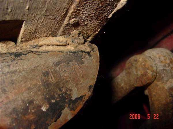
Carl Biederman from Anoka, Minnesota has found several Model “A” vehicles with some letter/s followed by a number stamped into the rear area areas. The locations of the stampings have been noted on the rear end axle housing, top of the rear frame cross member and the right rear corner of the rear frame cross member (see picture below from Eldon Frisk).
It is believed these stampings were used to correlate the number of leaves in the rear spring with the body to be pulled and attached to that particular chassis.
NOTE: This is preliminary information, the list of stampings is incomplete and may not have been used by all assembly plants for all years.
Following are the stampings noted to date with their interpretations:
|
Stamping
|
Body Style
|
Rear Spring Leaves
|
|
R7
|
Roadster
|
Seven leaves
|
|
C8
|
Coupe
|
Eight leaves
|
|
OCPU0
|
Open Cab Pickup
|
Ten leaves
|
|
T0
|
Tudor
|
Ten leaves
|
|
TS0
|
Town Sedan
|
Ten leaves
|
|
FD0
|
Fordor
|
Ten leaves
|
Specifications and License Data
|
Engine Type
|
4 cylinder, L head
|
|
Engine Material
|
Gray Cast iron
|
|
Engine Cylinders
|
4, cast engine block, 1/8” offset
|
|
Engine Firing Order
|
1, 2, 4, 3
|
|
Engine Displacement
|
200.5 cu. inches
|
|
Diameter of Cylinder Bore
|
3.876
|
|
Diameter of Pistons
|
3.8745
|
|
Stroke
|
4.125
|
|
Crankshaft Material
|
Ford Carbon Manganese Steel
|
|
Length
|
26.25
|
|
Crank Gear
|
Steel, 25 spiral-cut teeth
|
|
Diameter of Crankshaft
Main Bearings
|
1.624
|
|
Diameter of Crankshaft
Pin Bearings
|
1.499
|
|
Horsepower
|
SAE rating, 24.03
Brake, 40 @ 2200 RPM
|
|
Torque
|
128 ft-lbs @ 1000 RPM
|
|
Compression ratio
|
4.22 to 1
|
|
Compression
|
76 psig
|
|
Flywheel
|
Cast iron
|
|
Flywheel Ring Gear
|
Steel, 14.2 inch outside dia, 112 teeth
|
|
Camshaft Bearings
|
early 5 bearings (later 3), 1.560
|
|
Camshaft Lift
|
0.302
|
|
Camshaft Gear
|
Phenolic resin material, 50 spiral-cut teeth
|
|
Valve lift
|
0.287
|
|
Valve Clearance
|
0.010 to 0.013
|
|
Breaker point gap
|
0.018 to 0.022
|
|
Spark plug gap
|
0.035
|
|
Oil System
|
Engine lubricated by gear pump, splash and gravity feed. Capacity 5 quarts.
|
|
Transmission
|
Selective sliding rear type, three speeds forward and reverse. Capacity 1 pint.
|
|
Clutch
|
Early to mid 28, Multiple disc
Later 1928 to end – Single Plate
|
|
Brakes
|
Four wheel internal expanding service brakes operated by the foot petal. Also an emergency or parking brake on both rear wheels operated by the emergency brake lever. Emergency brakes are entirely separate and distinct from the four- wheel service brakes. Total braking surface 225 1/2 sq inches.
|
|
Cooling System
|
Pump and thermo-syphon. Capacity 3 gallons.
|
|
Water pump shaft end play
|
0.006 to 0.010
|
|
Carburetor
|
Zenith design, cast iron; manual adjustment and choke control on dash panel
|
|
Gasoline tank
|
10 gallons
|
|
Rear Axle
|
Three-quarter floating type. Torque tube drive. Spiral bevel drive pinion and gear. Capacity 1.5 pints
|
|
Wheel Base
|
103.5 inches
|
|
Turning radius
|
17 ft, circle 34 ft.
|
|
Tread
|
56 inches
|
|
Road Clearance
|
9.5 inches
|
|
Generator
|
Average Summer Charging Rate
– 6 to 8 amps @ 1500 RPM
Average Winter Charging Rate
– 10 to 12 amps @ 1500 RPM
|